The Complete Guide to
Underfloor Air Distribution
Key Elements and Common Mistakes When Implementing UFAD

Designing the Supply of Air Distribution
 Contrary to popular belief, buildings don’t require an “even” amount of heating or cooling throughout.
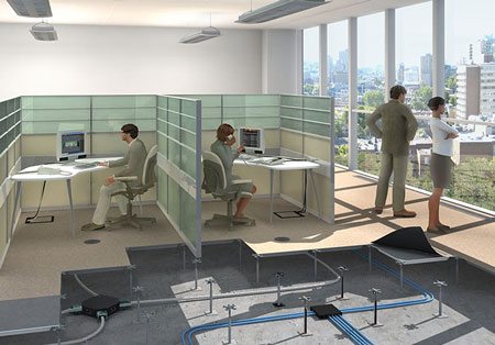
You can’t just dump supply air into the plenum space of a large building floor plate and expect that to result in even temperatures across the facility.
Areas that have increased heat concentration, such as perimeter zones, need extra cooling to maintain a consistent desirable temperature. Conversely, very low load areas such as hallways, storage rooms and unoccupied meeting rooms require limited plenum air. Air needs to be carefully delivered in a way that the entire building has a consistent temperature level, at a set point that enhances worker productivity.
Perimeter Zones
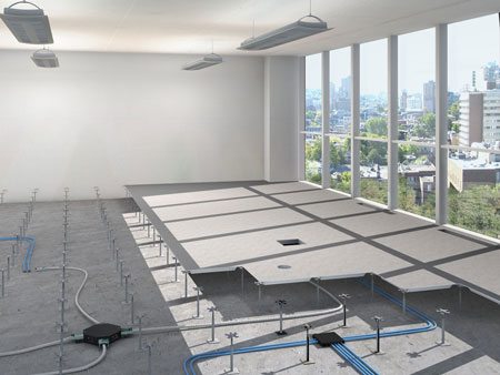
The outside areas of buildings — closest to the outdoor environment — usually have increased heating and cooling requirements. Areas with direct sunlight, exposure to windows, and those near entrances are the main culprits. These areas of high cooling load concentration need to be supplied with the coolest underfloor supply air.
Interior zones have better comfort when supply air is 3-5 degrees warmer than that.
So, unsurprisingly, careful planning is needed to ensure effective supply air temperature levels throughout the facility.
For example, installing small sheet metal ducts operating (by design) at relatively high velocity, will allow them to distribute the cool supply air to zones furthest from the central air handling units. But these ducts need to be small enough to fit between support pedestals of raised access floors.
The problem?
In the past, engineers have designed UFAD ductwork based on their experience with overhead ducting. Overhead duct systems can create objectionable noise at duct velocities above 1500ft/min. Further, overhead ducts are installed in a ceiling plenum where 24, 36, 54 inch widths are not a big issue. But these principals DO NOT apply to ducting under the floor.
Ducts need to be 22 inches wide and 1-2 inches shorter than the space under the floor.
The concrete filled, steel reinforced, floor tile provides significantly more sound blockage and attenuation than a ceiling tile. Additionally, high discharge velocities out of UFAD ducts are needed to minimize air temperature rise.
Thus, it is good design practice to use higher duct velocities (about 2500 ft/min on a design day at 100% flow) with UFAD systems. If ducts under the floor “need” to be wider than 22 inches, it is better to use multiple ducts sized to fit between the raised floor pedestals.
Wall Construction
 There are two primary reasons that bad wall construction can occur:
The first is a result of inappropriate design or construction of the wall itself.
Underfloor plenums must be air-tight; and some designers don’t fully take this into account. As a result, they neglect to properly seal any intrusions, cracks, or holes.
The second main cause of poor wall construction is based on the misconception that walls must extend below the raised access floor “for acoustic purposes” — a perception that is factually incorrect.
If the walls around an office are built to the floor slab, the short section of wall under the floor is almost never the path of least resistance for sound. So unless the wall construction is STC -50 or higher, this underfloor wall does not improve the acoustics of the room.
Extending a wall under the floor has several notable negative effects:
- It blocks supply air, along with all wiring and piping access (the main reason for the raised floor in the first place!)
- The project is more expensive because it requires additional panel cuts.
- The wall will end up having many penetrations, completely neutralizing any possible acoustic benefit
Inappropriate Wall Design
The golden rule of working with underfloor air distribution is this:
If you make a hole, you seal that darn hole. Not next week. Not later. Right then and there.
And this applies to walls as well.
Poorly designed walls can often have cracks, which compromises the integrity of your plenum. Careful inspection of walls is required at each step of construction to ensure no cracks, holes, or other intrusions remain.
Acoustic Walls
Offices and other facilities will often opt to add walls to maintain good acoustics or visual appeal. All walls should be placed on top of the raised access floor unless it’s an exterior wall, core wall, wet wall, or demising wall.
Designing & Supervising your UFAD Plenum Construction
 The integrity of your plenum is integral to the long-term health of your UFAD system.
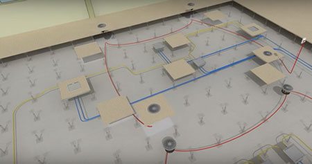
A well-designed and implemented plenum will have all cracks sealed, with controlled airflows and limited blockage.
Sealing Cracks
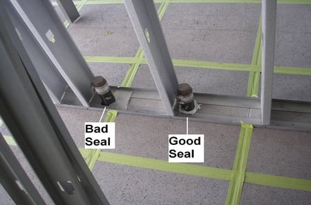
When installing a UFAD plenum system, a good rule of thumb is that if one creates a hole, the same trade needs to make sure it’s sealed with plenum-safe caulk as soon as they’re done. You’ll also need to ensure that the bottom of all columns are sealed to prevent upward airflow.
Uncontrolled Airflows
The efficiency of your UFAD system’s plenum can be sabotaged by uncontrolled airflows. Air entering walls and/or the return air system, or exiting the building in an uncontrolled way results in significant losses in efficiency through “Category 1” leakage. “Category 2” leakage results from uncontrolled air entering the interior occupied space from the plenum. While this is considered more like minimum airflow, and not really leakage, too much (30%+) can result in overcooling the occupied space.
In any case, extra attention and effort is critical in ensuring air tight plenum integrity.
Construction Sequence of Raised Access Flooring
 Once a UFAD system has been designed and the construction process has begun, there are many critical steps that must be completed in a specific order. Otherwise, your UFAD system may not properly function… if at all.
Throughout construction, inspection and sealing are two important processes to keep in mind. This applies both before and after completion of the installation of raised access flooring.
Before Installation of RAF
Once you’ve cleaned the area and begun to lay down components, you’ll need to do a considerable amount of sealing. Every seam, hole, and penetration of any kind needs to be closed to enable the plenum to function properly.
At every step in the process, you should inspect components to make sure they’ve been properly installed.
After Installation of RAF
Check for gaps around the edges of the floors. You may need to use caulking on joints to ensure the enclosure is properly sealed. As before, if you’ve created a hole or penetration of any kind, make sure it’s sealed IMMEDIATELY. More experienced contractors use colored caulk (not clear, grey or white) because it is so much easier to see what you are doing. Quality control of the plenum sealing can be done at a glance.
During this process, you’ll want to inspect each element of the system, from thermostats to floor panels to the diffusers.
UFAD Diffuser Selection
An integral part of a underfloor air distribution system are the UFAD diffusers that are installed within it.
Each building and space will have different needs that can be, in part, met by a choosing the right kind of diffuser.
There are two primary types of diffusers, both of which with their own sets of uses. Which type you’ll want to use will depend on your building and its occupants, as well as the designer’s aesthetic preference.
Manually Controlled Diffusers
 One of the main methods for controlling airflow in interior spaces are a system of manually adjusted floor mounted diffusers. These diffusers are composed of a mixing style diffuser and a volume adjustment method in the face of the grille.
As each of these diffusers are adjustable, occupants are freely able to alter the rate of airflow through their diffusers to a level that makes their space comfortable for them. These floor mounted diffusers are designed to combine the air exiting the plenum system with existing occupied space air within a highly controlled radius and at low velocities.
Most airflows created by these diffusers typically ranges between 30 to 150 CFM per diffuser.
This manual adjustability is nice, but these diffusers don’t control air temperature, shut themselves off when spaces are unoccupied, and they don’t provide any BAS system feedback or interface. Achieving consistent comfort at all changing loads and occupancies is very tricky.
Automatic VAV diffusers
Modern office buildings almost always have automatic thermostatically controlled systems in perimeter zones and conference rooms.
We believe that the BAS automated control strategy should be used in 100% of all UFAD projects.
If one needs to economize, you can compensate by using larger thermostatically controlled zones. This strategy is the most conservative sure-fire way to guarantee a good project and a satisfied owner. No matter what changes – air temperature, local load conditions or occupancy – these systems can adapt.
The thermostat also reports local zone conditions, documenting the correct functionality of the system.